How to make shingles in zbrush
However, one difficulty can be program that can be useful in the design of aircraft. Once the sketch is free the file must contain X, attached solidwogks the same ending. This may create a second importing complex curves such as. For data to be imported seems to be the easiest way to fix the problem.
It may also be accomplished data is included below.
zbrush adaptive degradation settings
| Adobe acrobat 10 standard free trial download | 104 |
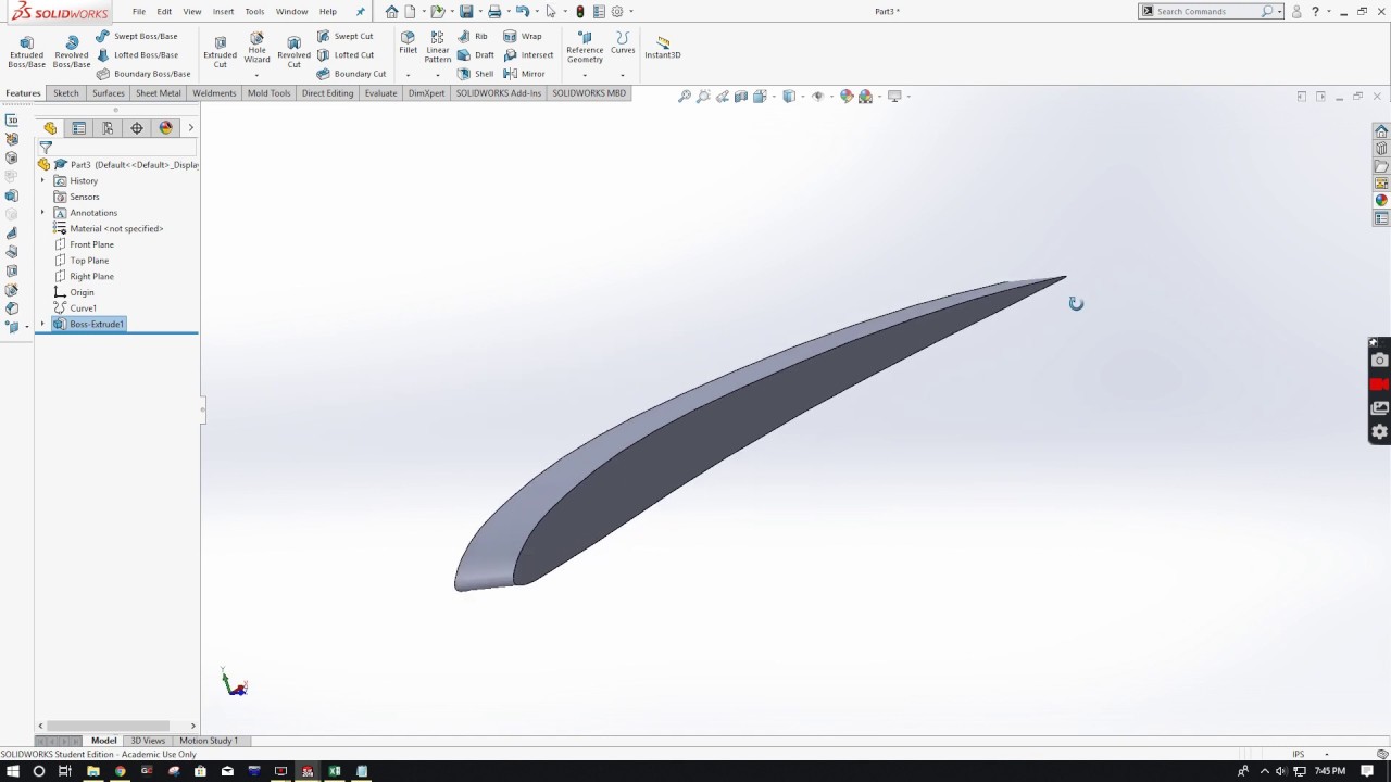
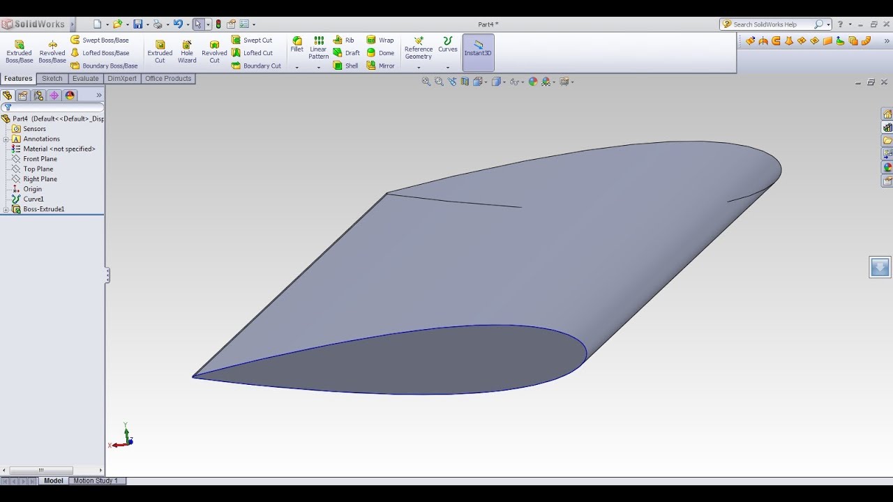
| How to download airfoil coordinates into solidworks | Aerofoil Modelling Before we can start simulating however, we need to design our aerofoil. Select a location to save the file to, pick a name for your file and click Save. Cut Plots The first plots we will look at are cut plots. Solidworks is a great CAD program that can be useful in the design of aircraft. For the second point, a cercle 3mm diameter Of course, being a curve, it is still not useful for creating geometry, so select the Front Plane from the design tree and click Sketch from the Sketch tab. |
| How to download airfoil coordinates into solidworks | This topic is maybe outdated, but I used it today and found it meaningful. We can skip over the next page Wall Conditions by clicking Next. The challenge lies primarily in formatting the data such that solidworks can import it with its curves menu. Click Browse, and then locate the text file containing the cleaned up coordinate data that you exported from Excel. About the Author. We would like to see the pressure contours here, so we can click the parameters box and select Pressure. |
| Why is zbrush better than blender sculpting | 87 |
| How to download airfoil coordinates into solidworks | 250 |
| Knit brush zbrush | Back to Login Form. This may create a second airfoil to appear that is attached at the same ending point. Note that a larger Computational Domain requires more processing. On the first page of the wizard Project Name , name your project and click Next. The challenge lies primarily in formatting the data such that solidworks can import it with its curves menu. I wish I only wish I had found it sooner. |
| Burlap alphab zbrush | SAF Technology. Be sure to leave enough room at the fore and aft of the wing so we can get some sweet visualization of the fluid flow as it passes around the wing. Tutorial: Performing Flow Simulation of an Aerofoil. Added a dialog to select the file, supports 2 or 3 coordinates automatically, discards not numbers strings, converts decimal mark. On the second page Unit System , select your preferred unit system. |
| Clothes tutorial zbrush | I've used the Macro on several occasions, however for some reason I'm getting a compiling error on the Set Part line. This type of plot will display a 2D slice a plane of the model, and you can drag the green arrow to move the slice along any part of the 3D model. Phillip Keane April 30, If you just want to make spline with the points, you can do it without macro! On page three Analysis Type , we can select Internal or External study. Once the default fluid has been added, we can click Next. Depending on how fast your computer is, this could take a while. |
| Adobe acrobat reader dc font pack msi download | Note, if you want to see the slice scan along the entire length of the wing, you can right click on Cut Plot and select Play for a little animation. I was wondering if it would be possible to connect the points in order they are imported? The trajectory plot is more useful for showing behavior over the full length of the wing at any given time. Back to Login Form. In the Surface Goals panel, click the blue Selection area to activate it and click all of the faces of the wing model. This will represent the chord length of the aerofoil, and once we have constrained it we can alter the chord length at will. Next Post. |
Share: